mirror of
https://github.com/qmk/qmk_firmware.git
synced 2024-12-28 04:19:56 +00:00
56 lines
2.2 KiB
Markdown
56 lines
2.2 KiB
Markdown
|
|
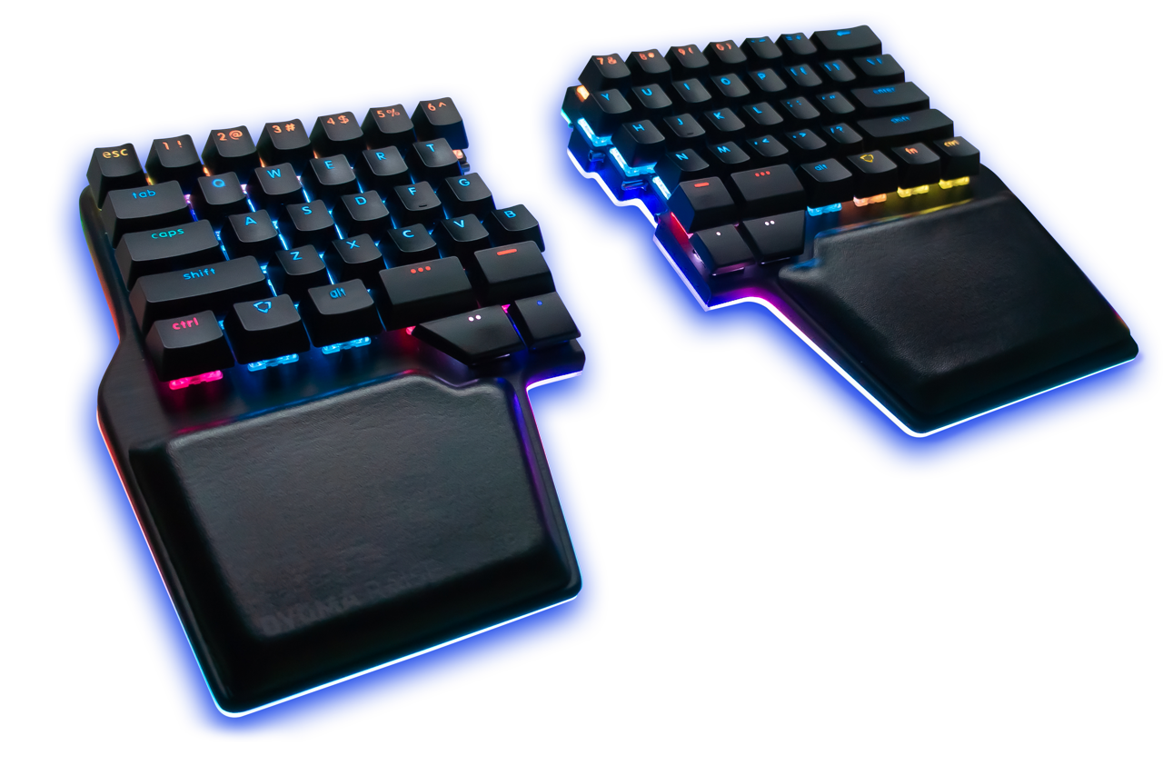
# Raise
|
||
|
|
|
||
|
|

|
||
|
|
|
||
|
|
* Keyboard Maintainer: [ibash](https://github.com/ibash)
|
||
|
|
* Hardware Supported: [F411 Blackpill](https://github.com/WeActTC/MiniSTM32F4x1) with the [Dygma Raise](http://www.dygma.com)
|
||
|
|
* Hardware Availability: See below
|
||
|
|
|
||
|
|
|
||
|
|
Make example for this keyboard (after setting up your build environment):
|
||
|
|
|
||
|
|
make handwired/dygma/raise/ansi:default
|
||
|
|
|
||
|
|
Flashing example for this keyboard:
|
||
|
|
|
||
|
|
make handwired/dygma/raise/ansi:default:flash
|
||
|
|
|
||
|
|
See the [build environment setup](https://docs.qmk.fm/#/getting_started_build_tools) and the [make instructions](https://docs.qmk.fm/#/getting_started_make_guide) for more information. Brand new to QMK? Start with our [Complete Newbs Guide](https://docs.qmk.fm/#/newbs).
|
||
|
|
|
||
|
|
## Hardware
|
||
|
|
|
||
|
|
QMK does not currently support the [Dygma Neuron](https://dygma.com/products/neuron-black) because QMK does not support SAMD21 which the Neuron has.
|
||
|
|
Instead this code uses a [STM32 Blackpill](https://github.com/WeActTC/MiniSTM32F4x1) to create a Neuron replacement.
|
||
|
|
|
||
|
|
## Required Hardware
|
||
|
|
|
||
|
|
1. [STM32 Blackpill from WeAct Studio](https://github.com/WeActTC/MiniSTM32F4x1) (via [aliexpress](https://www.aliexpress.com/item/1005001456186625.html) or [adafruit](https://www.adafruit.com/product/4877)).
|
||
|
|
|
||
|
|
2. 2x USB-C breakouts (via [keeb](https://keeb.io/collections/diy-parts/products/usb-c-breakout-board) or [adafruit](https://www.adafruit.com/product/4090)).
|
||
|
|
|
||
|
|
3. 2x 2.7KΩ resistors (via [digikey](https://www.digikey.com/en/products/detail/yageo/CFR-25JB-52-2K7/684)).
|
||
|
|
|
||
|
|
4. Breadboard or PCB proto board, wires, solder, etc.
|
||
|
|
|
||
|
|
## Wiring
|
||
|
|
|
||
|
|
Briefly each raise hand uses I2C to communicate with the Neuron:
|
||
|
|
|
||
|
|
1. USB D+ is the I2C clock line.
|
||
|
|
2. USB D- is the I2C data line.
|
||
|
|
3. The resistors are pullup resistors for the I2C lines.
|
||
|
|
4. Each hand draws power from the USB port.
|
||
|
|
|
||
|
|

|
||
|
|
|
||
|
|
<p float="left">
|
||
|
|
<img src="https://i.imgur.com/GvXfnpf.jpg" width="200">
|
||
|
|
<img src="https://i.imgur.com/kFKFjrU.jpg" width="200">
|
||
|
|
</p>
|
||
|
|
|
||
|
|
We are also prototyping a [custom pcb](https://www.reddit.com/r/DygmaLab/comments/ojgm95/pcb_for_running_qmk_on_the_raise/?utm_source=share&utm_medium=web2x&context=3).
|
||
|
|
|
||
|
|
<p>
|
||
|
|
<img src="https://i.imgur.com/xfzIxkW.png" width="200">
|
||
|
|
</p>
|